Conducting root cause failure analysis on a failed mechanical seal can in the long run minimize mean time between failure (MTBF) and operating costs by preventing repeat premature failure. If you can find the culprit and resolve the issues, you can prolong the life of the next mechanical seal and save time and money.
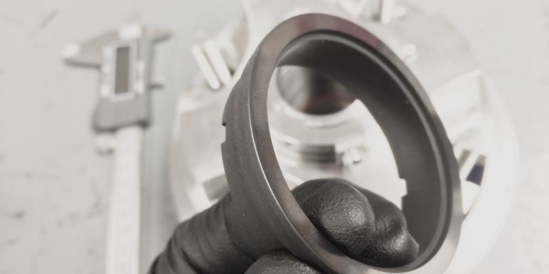
A tremendous amount of useful information is available from a failed mechanical seal. With nothing more than your eyes and a measuring device like a dial or digital caliper, you can identify failure modes with great dependability and detail. With this information you can decide if any corrective measures are worth the resources required. In many cases, the payback is many times the outlay in a very short period of time.
And because RCFA (Root Cause Failure Analysis) provides evidence rather than conjecture, it can support the changes needed when other departments are involved. Following are the steps to examine a failed mechanical seal.
-
Keep and examine the entire seal assembly.
Whether seal parts or entire seals will be repaired or not, whether they are repairable or not, they have much information to reveal.
-
Don't clean the seal.
Unless required by Process Safety Management, don’t clean the seal before examining it. Cleaning may wash away critical evidence.
-
Examine the pump for clues.
Whenever possible, examine shafts, sleeves, bearings, gaskets and other pump parts. Doing this, you can support your interpretation of what you see on the seal parts or even change it as necessary.
-
Shafts and Sleeves
Look for fretting - damage caused by O-rings. Measure the diameter to ensure dimensional tolerance of +/- 0.002."
-
Bearings
If it is discolored black, it is evidence of heat. If it is discolored brown, it is evidence of contamination.
-
Gaskets
Look to see if gaskets are hard, dissolved, missing, or extruded.
-
Other Pump Parts
Look at the impeller, casing, and rear cover for excessive wear. Compare dimensions with tolerances show in the IOM.
-
-
Try to get an idea of how long the seal ran before it leaked.
Knowing when the seal leaked narrows down the cause of failure. The critical division is whether the seal leaked when liquid was brought to it or before start up, or after the pump started running
Why is this important? If it leaked when initially flooded or before startup, it was due to one or more of the following causes:
-
One or more seal faces were not flat enough to seal.
Normal seal flatness is just 2 helium light-bands or 23 millionths of an inch! Corrective action here would be to test the seal assembly in a pressure testing rig before installation and/or to inspect the seal faces with a monochromatic light and an optical flat.
-
A secondary sealing mechanism failed
A gasket or O-ring was damaged during installation, is missing, or is the wrong size. Shaft O-rings can get cut during installation or it can even twist and roll during installation, opening up a path of leakage.
-
The seal is not in the proper location on the shaft.
Most seals require a working length with only plus or minus .030” tolerance. The working length must come from the factory. There is almost no reliable method to determine the working length of a seal when in the field. This is one reason why cartridge (pre-measured) seals have become so popular.
-
Some other seal part is missing, the wrong size or installed incorrectly.
If you have a PTFE wedge seal design, the wedge can be in backwards or be an incorrect size. An O-ring can be the wrong cord diameter. An O-ring groove could have been machined incorrectly.
Conversely, if the seal leaked after startup, it was not due to one or more of those four issues. You can eliminate these four issues and seek other causes.
-
-
Examine the wear track on the seal faces.
This is the mark made by the mechanical seal rotating face rubbing against the stationary face. The seal faces are the lapped parts of the seal that rub against each other. The wear tracks may contain clues that may identify the reason the seal failed. Double seals will have two sets of rotary and stationary faces, so check them both (but keep each set together)
Refer to the diagrams inRoot Cause Failure Analysis - Interpret Wear Tracks, where we show you what to look for when examining the wear tracks.
-
Inspect the mechanism that rotates the seal.
Look for signs of wear on the rotating mechanism. This could be pins, lugs, set-screws, a spring or rubber or metal bellows. These parts can be worn when the faces are pressed together too tightly. The faces jam together then break free. This repeats over and over until the drive lugs or pins get worn. This happens when there is insufficient lubrication between the faces.
-
Check to make sure the mechanical seal is not over-compressed.
The working length of the seal must be provided by the supplier. It is almost impossible to determine the correct working length in the field. And, this is almost always just a plus or minus .030” tolerance.
-
You may have too much system pressure acting on the seal face.
This can happen if you are using an unbalanced seal rather than a balanced seal. Balance refers to hydraulic balance not mechanical balance.
-
Process fluid has no lubricating properties
Hot water, lignin and other liquids have little or no beneficial lubricating properties, which can cause slip-sticking.
-
The face materials themselves could be the problem.
Tungsten-carbide running against tungsten-carbide is not always the best choice for abrasive service.
-
Cavitation
If the pump is cavitating, the faces are literally blown apart then they come back together fast when the pressure drops. This jams the seal faces together.
-
Vertical pump configuration.
If a pump is vertical, any entrained air will eventually makes its way to the highest point inside the pump. This is often where the seal faces are. If this happens, the faces run dry. Venting this area or having circulation will prevent this.
-
-
Inspect the springs.
Broken springs are almost always a result of stress corrosion. This happens when stainless steel is flexed in the presence of halogens such as fluorine, bromine, iodine and others. Stress corrosion is actually a chemical attack where small cracks or fissures are created in the stainless steel. Particles can enter this crack and when the springs tries to compress a strong mechanical force is created that can break a spring. Most high-quality industrial mechanical seals have been converted to Hastelloy C springs. Hastelloy C can withstand halogens without cracking. It is interesting to know that springs and metal bellows can actually flex almost indefinitely without breaking if they are flexing within the limits of travel that they were designed for.
Clogged springs indicate that solids in the process flow have accumulated. Seals with multiple small springs are more prone to clog than seals with one large spring or metal bellows.
-
Inspect the O-rings.
O-ring materials can include various compounds of Buna-N (Nitrile), fluoroelastomers such as Viton, EPR/EP/EPDM, and perfluoroelastomers such as Kalrez or Chemrez.
-
If an O-Ring has dissolved or is swollen or sticky, it is evidence of chemical incompatibility.
This chemical incompatibility could be from the process fluid itself. Keep in mind that chemicals become approximately twice as aggressive for every 20 degree rise in temperature. The stuffing box area of a pump can be several hundred degrees F higher than the temperature of the discharge. Additionally, the problem can be a flush fluid or even what a pump is cleaned with. For applications where there is no available elastomer that can handle the chemicals the sealing device will see, you can select a mechanical seal with either PTFE or flexible graphite secondary seals. Neither PTFE nor flexible graphite is a true elastomer. They are considered “plastic” in the sense that when deformed they do not recover their original shape.
-
If an O-Ring is hard, it is evidence of heat.
Keep in mind that temperature limits published for various O-Ring materials are based on hot air only. These limits are for ultimate failure. Lower temperatures can start the degradation of an elastomer. Again, the temperature in a stuffing box can be hundreds of degrees F higher than at the discharge. Only a temperature gauge connected to the stuffing box, preferably with a tell-tale to indicate the highest temperature reached, can verify how hot the stuffing box gets. The solution for heat is either to reduce the temperature the mechanical seal and its O-Rings actually experience or to select an elastomer with suitable temperature resistance.
-
If an O-Ring is deformed it is also a signal that it was exposed to temperatures higher than it could handle.
Measure the O-Rings from the inside to the outside and from the top to the bottom. This determines the actual deformation. Some deformation is normal. However, if the O-Ring is deformed to where your measurements are at or lower than the nominal dimensions, the O-Ring can no longer seal. Following is some specific dimensional information:
- -000 series O-rings, from -004 through -050, have an actual cord diameter of .070”. They are designed to compress to about .0625”, so they are referred to as a nominal 1/16” O-Ring.
- -100 series O-Rings, from -102 through -178, have an actual cord diameter of .103” and are referred to as 3/32” nominal.
- -200 series O-Rings, from -201 through -284, have an actual cord diameter of .139” and are referred to as 1/8” nominal.
- -300 series O-Rings, from -309 through -395, have an actual cord diameter of .210” and are referred to as 3/16” nominal.
- -400 series O-Rings, from -400 through -475, have an actual cord diameter of .275” and are referred to as ¼” nominal.
Note: Metric O-rings are sized by their actual cord diameter and their actual inside diameter.
-